Beagle-Solar-A-Car
https://code.google.com/p/texas-instruments-intern-design-competition-2013/
Introduction

The aim of this project is to build a solar energy powered autonomous car. Resistive matching has been employed to extract maximum energy from a solar panel, with minimal complications. This is done in order to maximize the amount of energy that is transferred from the solar cell into a Li-ion battery. This battery is used to drive an H-bridge motor controller which is controlled through the BeagleBone.


Schematic
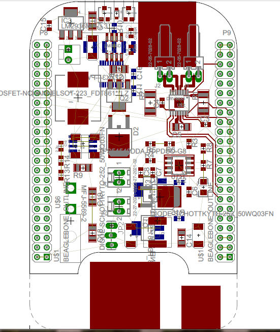


PCB

Code
Header File
#! /bin/sh#This script initializes the pin muxing modes to bring out the PWM and UART signals to the desired header pins.
#Must be executed manually from the command line after booting.
#Would be nice to have this done automatically at boot time, but I've had trouble finding a solution that works.
#Enable UART4 at header pins P9_11 (RX) and P9_13 (TX).
echo uart4 > /sys/devices/bone_capemgr.9/slots
echo am33xx_pwm > /sys/devices/bone_capemgr.9/slots
#Enable header pins for PWM0A at P9_31 respectively. (DC Motor)
echo bone_pwm_P9_31 > /sys/devices/bone_capemgr.9/slots
#Enable header pins for PWM1A at P9_14 respectively. (DC Motor)
echo bone_pwm_P9_14 > /sys/devices/bone_capemgr.9/slots
#Enable header pins for PWM2A at P8_19 respectively. (Servo)
echo bone_pwm_P8_19 > /sys/devices/bone_capemgr.9/slots
#Setup further options for UART communication
stty -F /dev/ttyO4 raw
#Poll UART4 for motor position and speed data without interrupting the main script timing
#while 1
#do
# cat /dev/ttyO4 > /var/lib/cloud9/rcvd.txt
#done
Main Code
var b = require('bonescript');var servo_per = 20000000; //20000000 ns = 50 Hz
var servo_pos = 0; //-100 is far left, 0 is center, 100 is far right
var servo_step = 10;
var sig_speed1 = 0;
var sig_speed2 = 0;
var zc_timeout1 = 10;
var zc_timeout2 = 10;
var motor1_per = 50000; //100000 ns = 20000 kHz
var motor2_per = 50000;
var motor1_dc = 50;
var motor2_dc = 80;
var motor1_step = 10;
var motor2_step = 10;
var motor1_state = 0; //1 for forward, 0 for stopped, -1 for reverse
var motor2_state = 0;
var motor_dc_max = 100;
//Initialize PWM periods and polarities
b.writeTextFile('/sys/devices/ocp.2/pwm_test_P8_19.14/period',JSON.stringify(servo_per));
b.writeTextFile('/sys/devices/ocp.2/pwm_test_P8_19.14/polarity','0');
b.writeTextFile('/sys/devices/ocp.2/pwm_test_P9_31.12/period',JSON.stringify(motor1_per));
b.writeTextFile('/sys/devices/ocp.2/pwm_test_P9_31.12/polarity','0');
b.writeTextFile('/sys/devices/ocp.2/pwm_test_P9_14.13/period',JSON.stringify(motor2_per));
b.writeTextFile('/sys/devices/ocp.2/pwm_test_P9_14.13/polarity','0');
b.pinMode('P9_29', b.OUTPUT);
b.pinMode('P9_16', b.OUTPUT);
b.pinMode('P9_42', b.OUTPUT);
b.digitalWrite('P9_29', b.LOW);
b.digitalWrite('P9_16', b.LOW);
b.digitalWrite('P9_42', b.HIGH);
setInterval(updatePos,10); //Loop every 5 ms
setInterval(rcvData,2000);
function rcvData()
{
if(sig_speed1 == 100)
{
sig_speed1 = -100;
}
else
{
sig_speed1 = 100;
}
if(sig_speed2 == 50)
{
sig_speed2 = -50;
}
else
{
sig_speed2 = 50;
}
}
function updatePos()
{
//Motor control - ramp up motor duty cycle instead of instantly responding to phone's commands
//Also briefly stop the motors at zero-cross before changing directions
//If P9_29/P9_16 is low, motor is currently ordered forward and PWM DC is normal (polarity = 0)
//If P9_29/P9_16 is high, motor is currently ordered reverse and PWM DC is inverted (polarity = 1)
//If motor is currently moving in the same direction it is commanded (no zero-touch or zero-cross)
if((motor1_state == 1 && sig_speed1 > 0) || (motor1_state == -1 && sig_speed1 < 0))
{
if(sig_speed1 * motor1_state > motor1_dc) //If duty cycle needs to increase
{
if(sig_speed1 * motor1_state - motor1_dc < motor1_step && sig_speed1 * motor1_state < motor_dc_max)
{
motor1_dc = sig_speed1 * motor1_state;
}
else if(motor1_dc + motor1_step < motor_dc_max)
{
motor1_dc += motor1_step;
}
else
{
motor1_dc = motor_dc_max;
}
}
else //If duty cycle needs to decrease (or stay the same)
{
if(motor1_dc - sig_speed1 * motor1_state < motor1_step)
{
motor1_dc = sig_speed1 * motor1_state;
}
else
{
TI Parts Used
Used to provide a gate-driving signal for the buck-boost
regulator. This is configured as an approximately 57KHz oscillator.
DRV8833 - 2A
Low Voltage Dual Brushed DC or Single Bipolar Stepper Motor Driver (PWM Ctrl)
LM2936 -
Ultra-Low Quiescent Current LDO Voltage Regulator
Used to provide a regulated 5V for the timer. This allows steady
operation at solar voltages up to 40V
TPS54360 - 60 V
Input, 3.5 A, Step-Down DC-DC Converter with Eco-mode
Used to provide an efficient 5V for the BeagleBone Black at
battery voltages as low as 6V.
Good job :) Congratulations!
ReplyDelete